UML Deployment Diagrams Examples
Here we provide some examples of UML deployment diagrams:
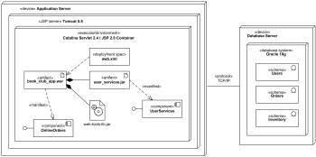
Purpose: An example of UML deployment diagram for a web application.
Summary: Book club web application artifact book_club_app.war is deployed on Catalina Servlet 2.4 / JSP 2.0 Container which is part of Apache Tomcat 5.5 web server.
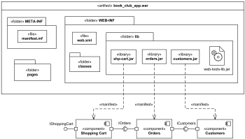
Purpose: An example of manifestation diagram for a web application.
Summary: Web application archive artifact book_club_app.war contains several files, folders and subfolders. Several components are shown on the diagram manifested (implemented) by jar archive files.
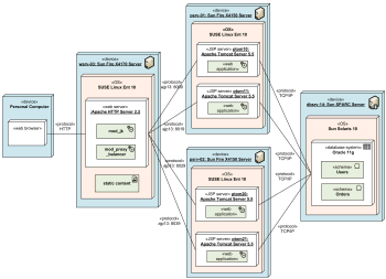
Purpose: An example of deployment diagram for J2EE web application with load balancing and clustering which shows specific server instances involved.
Summary: Incoming HTTP requests are first processed by Apache web server. Static content such as HTML pages, images, CSS, and JavaScript is served by the web server. Requests to JSP pages are load balanced and forwarded to 2x2 Apache Tomcat servers using both vertical and horizontal clustering.
Purpose: An example of UML deployment diagram with hardware and software load balancing and clusters.
Summary: An example shows 2 active hardware load balancers connected to 2 to 4 Sun Fire Servers. Each server has 3 instances of IBM WebSphere 7 J2EE application servers installed.
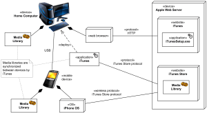
Purpose: An example of deployment diagram for Apple iTunes application.
Summary: Apple's iTunes application communicates with Apple iTunes Store. Customer can buy and download music, video, TV shows, audiobooks, etc. and store it in media library. Mobile devices like Apple iPod Touch and Apple iPhone update media libraries from home computer with iTunes through USB, or could download media directly from Apple iTunes Store using some wireless protocol.
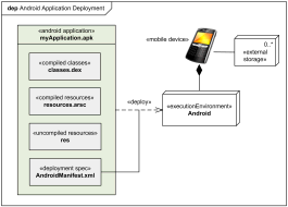
Purpose: An example of deployment diagram for Android application deployment.
Summary: Android SDK tools compile and package the code along with any required data and resource files into Android application archive file. The archive file represents one Android application to be deployed to the Android-enabled mobile devices.
 Web application network diagram example
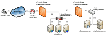
Purpose: UML provides no special kind of diagram to describe logical or physical network architecture of the designed or existing system. Deployment diagrams could be used for this purpose with elements limited mostly to devices with neither artifacts nor actual deployments shown.
Summary: This example of the network diagram shows network architecture with configuration usually called "two firewall demilitarized zone (DMZ)". DMZ is a host or network segment located in a "neutral zone" between the Internet and an organization’s intranet (private network). It prevents outside users from gaining direct access to an organization’s internal network while not exposing a web, email or DNS server directly to the Internet.
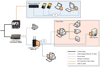
Purpose: An example of network architecture diagram for a home network.
Summary: Modern homes usually have a network of interconnected devices of different kinds and with various types of connections and communication protocols.
