Bank ATM
UML Composite Structure Diagram Example
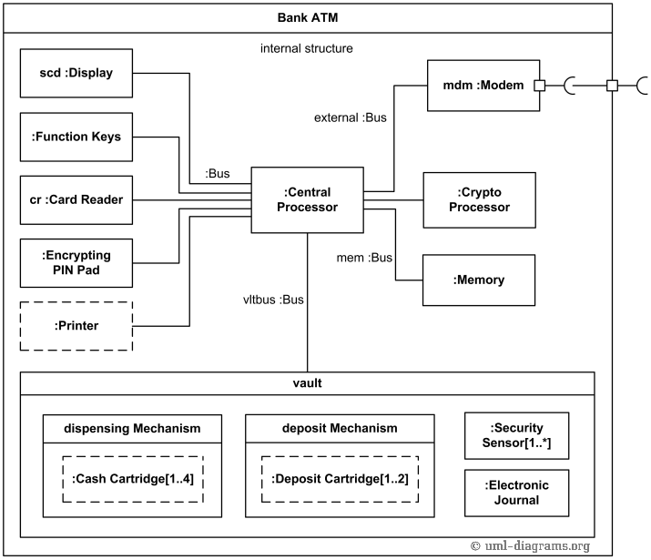
This is an example of UML internal structure diagram which shows composite structure of a bank Automated Teller Machine (ATM). The purpose of this diagram is to show internal structure of a bank ATM and relationships between different parts of the ATM.
Bank ATM is typically made up of several devices such as central processor unit (CPU), cryptoprocessor, memory, customer display, function key buttons (usually located near the display), magnetic and/or smartchip card reader, encrypting PIN Pad, customer receipt printer, vault, modem.

Bank ATM internal structure UML diagram example
Vault stores devices and parts which require restricted access, including cash dispensing mechanism, deposit mechanism, several security sensors (e.g. magnetic, thermal, seismic, gas), electronic journal system to maintain system log, etc. Cash dispenser includes several removable cash cartridges and deposit mechanism - removable deposite cartridges.
ATM is usually connected to the bank or interbank network via some modem (e.g. dial-up or ADSL) over a public switched telephone line or a leased line. Network interface card (NIC) could be used as a high-speed alternative in VPN connections.
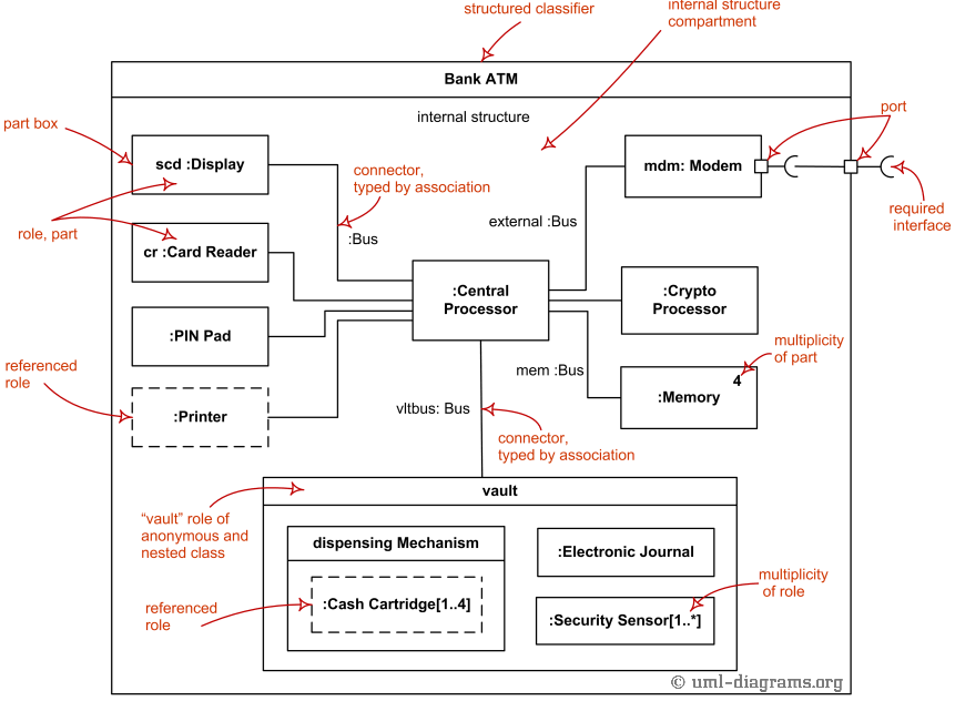
The overview diagram below explains the composite structure diagram with elements of internal structure of a structured classifier - roles, parts, connectors.

Composite structure diagram overview shows elements of internal structure of structured classifier - roles, parts, connectors.