UML Use Case Diagrams
Use case diagrams are usually referred to as behavior diagrams used to describe a set of actions (use cases) that some system or systems (subject) should or can perform in collaboration with one or more external users of the system (actors). Each use case should provide some observable and valuable result to the actors or other stakeholders of the system.
Note, that UML 2.0 to 2.4 specifications also described use case diagram as a specialization of a class diagram, and class diagram is a structure diagram.
Use case diagrams are in fact twofold - they are both behavior diagrams, because they describe behavior of the system, and they are also structure diagrams - as a special case of class diagrams where classifiers are restricted to be either actors or use cases related to each other with associations.
[UML 2.5 FTF - Beta 1] moved use cases out of behavior modeling to UML supplementary concepts. So, it is an unfortunate quandary what kind of UML diagrams use case diagrams are.
Business Use Case Diagrams
While support for business modeling was declared as one of the goals of the UML, UML specification provides no notation specific to business needs.
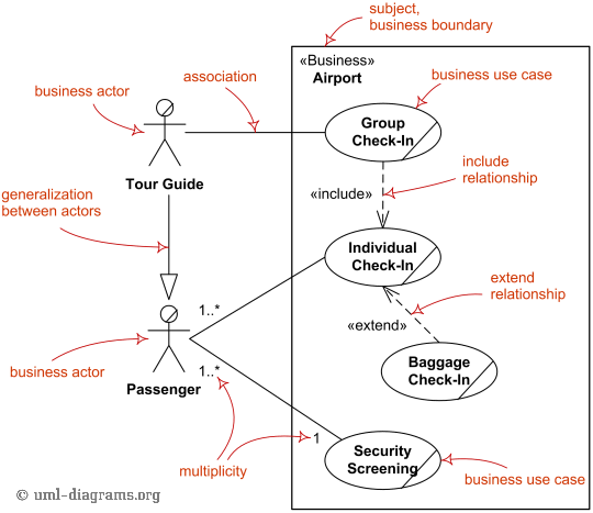
Business use cases were introduced in Rational Unified Process (RUP) to represent business function, process, or activity performed in the modeled business. A business actor represents a role played by some person or system external to the modeled business, and interacting with the business. Business use case should produce a result of observable value to a business actor.
Major elements of the business use case diagram are shown on the picture below. Note again, both business use case as well as business actor are not defined in UML standard, so you will either need to use some UML tool supporting those or create your own business modeling stereotypes.

Major elements of business use case diagram -
business actor,
business use case,
business boundary,
include
and extend relationships.
System Use Case Diagrams
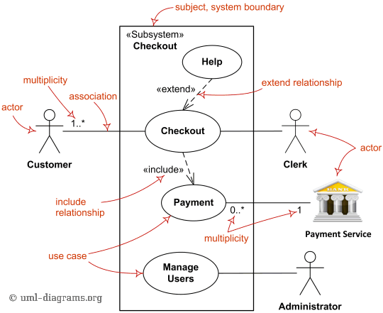
(System) Use case diagrams are used to specify:
- (external) requirements, required usages of a system under design or analysis (subject) - to capture what the system is supposed to do;
- the functionality offered by a subject – what the system can do;
- requirements the specified subject poses on its environment - by defining how environment should interact with the subject so that it will be able to perform its services.
Major elements of the UML use case diagram are shown on the picture below.
